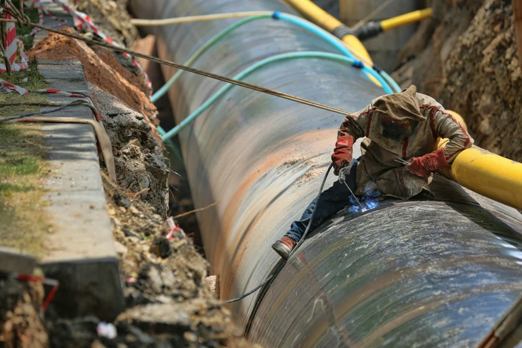
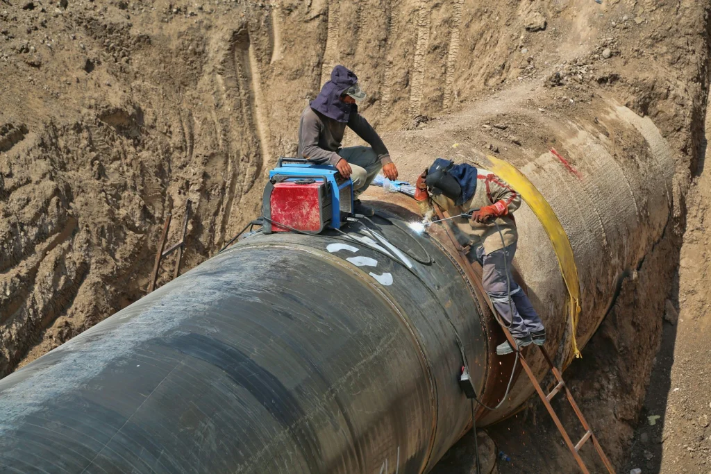
The five main weld inspection methods are visual testing (VT), dye penetrant (PT), magnetic particle (MT), ultrasonic (UT) and radiography (RT). VT, PT and MT find surface or near-surface flaws; UT and RT look inside the weld. The governing code, the material, the joint type and the consequence of failure decide which methods apply and how much of the weld gets examined.
Owners often hear these acronyms in bids and inspection plans without a clear sense of what each method actually proves. That matters, because a weld that passes one test can still contain a defect another test would catch. This guide explains how each method works, what it is good at, where it falls short and how to combine them sensibly on industrial welding jobs.
Key takeaways
- Visual inspection is required on virtually all code welding and catches a large share of problems early and cheaply.
- Dye penetrant works on almost any nonporous metal but only finds flaws open to the surface.
- Magnetic particle finds surface and slightly subsurface flaws, but only in ferromagnetic steels such as carbon and low-alloy grades.
- Ultrasonic testing is strong at finding planar flaws like cracks and lack of fusion; radiography is strong at volumetric flaws like porosity and slag.
- Acceptance criteria come from the construction code, not from the inspection method itself.
Why weld inspection is about more than the final weld
Inspection is most effective when it starts before the arc is struck. A good inspection program checks materials and certifications, joint preparation, fit-up, preheat, welder qualifications and the welding procedure in use. During welding, it checks interpass temperature, cleaning between passes and adherence to the WPS. After welding, it checks size, profile and surface condition, then applies nondestructive examination (NDE) as the code or contract requires.
Catching a bad fit-up before welding costs minutes. Finding the resulting lack of fusion on a radiograph costs a cut-out, a reweld and a re-shoot. That is why the procedure and qualification documents described in our WPS and PQR guide are part of the inspection story too.
What is visual testing (VT)?
Visual testing is the systematic examination of a weld with the eye, aided by lighting, magnification, mirrors, borescopes and measuring tools such as fillet weld gauges, hi-lo gauges for pipe alignment and undercut gauges. Despite its simplicity, it is the foundation of every inspection program.
What VT finds
- Surface cracks, surface porosity and arc strikes.
- Undercut, overlap, excessive convexity or concavity and underfill.
- Incorrect weld size or length, and misalignment between members.
- Incomplete penetration on accessible root sides, and excessive reinforcement.
Limits of VT
Visual testing cannot see internal defects. A weld can have a perfect cap and still contain porosity, slag or lack of fusion below the surface. On structural work under AWS D1.1, visual acceptance criteria are spelled out in the code, and inspection is often performed by an AWS Certified Welding Inspector. On many jobs, VT is the only method applied to most welds, which is why its quality matters so much.
How does dye penetrant testing (PT) work?
Liquid penetrant testing uses capillary action. After the surface is thoroughly cleaned, a colored or fluorescent penetrant is applied and left for a specified dwell time so it can seep into any surface-breaking discontinuities. The excess is removed, a developer is applied, and penetrant trapped in flaws bleeds back out to form a visible indication. Fluorescent systems are viewed under ultraviolet light and are generally more sensitive.
Where PT fits best
PT works on nearly any nonporous material: austenitic stainless steel, aluminum, nickel alloys, titanium and carbon steel. It is portable, inexpensive and well suited to root passes, back-gouged surfaces, weld overlays, small repairs and components that magnetic particle testing cannot examine. It is often used to confirm that a crack has been fully removed before a repair weld.
Limits of PT
The flaw must be open to the surface. Subsurface defects remain invisible. Surface preparation is critical: paint, scale, oil or metal smeared over a crack by grinding can close the opening and hide it. Penetrant systems also have temperature ranges set by the manufacturer, which matters on hot equipment or in cold weather.
How does magnetic particle testing (MT) work?
Magnetic particle testing magnetizes the part, usually with a portable yoke in the field, prods or coils. Where a crack or other discontinuity interrupts the magnetic field, flux leaks out of the surface. Fine iron particles, applied dry or suspended in liquid and available in visible or fluorescent forms, gather at those leakage points and outline the flaw.
Strengths of MT
MT is fast, relatively inexpensive and sensitive to fine surface cracks. It can also detect some discontinuities just below the surface, which penetrant cannot. It is widely used on carbon steel structural welds, fillet welds on equipment supports, lifting lugs, crane components and heavy equipment repairs, and it tolerates thin coatings better than PT in some cases.
Limits of MT
- It only works on ferromagnetic materials. Austenitic stainless steel and aluminum cannot be examined with MT.
- It detects flaws best when they run across the magnetic field, so technicians examine each area in two directions at roughly right angles.
- Depth capability is limited; it is not a volumetric method.
- Prods can cause arc strikes on the part, so some specifications restrict their use on sensitive materials.
What is ultrasonic testing (UT), and when is it used?
Ultrasonic testing sends high-frequency sound into the metal through a transducer and couplant. Sound reflects from interfaces such as cracks, lack of fusion or the back wall, and the instrument shows the reflection’s position and amplitude. For welds, angle-beam (shear wave) techniques are standard, because they send sound through the weld at an angle that intercepts typical flaw orientations.
Advanced UT: phased array and TOFD
Phased array ultrasonic testing (PAUT) electronically steers and focuses the beam, producing cross-sectional images and recordable data. Time-of-flight diffraction (TOFD) is especially good at sizing flaw height. Both create a permanent digital record, which conventional manual UT does not always provide.
Strengths of UT
- Excellent at finding planar flaws, including cracks, lack of sidewall fusion and incomplete penetration, which are the defects most likely to cause failure.
- Locates the depth of a flaw, helping repair crews excavate only what is needed.
- No ionizing radiation, so no exclusion zone and less disruption to nearby work.
- Needs access from one side only, and handles thick sections well.
Limits of UT
UT results depend heavily on technician skill and calibration. Coarse-grained welds in austenitic stainless and some nickel alloys scatter sound and are harder to examine. Thin sections, small-diameter pipe and complex geometry can be challenging. The surface must be reasonably smooth for good coupling. Separately, straight-beam UT thickness gauging is widely used to measure remaining wall thickness on corroded pipe and tanks, which is often what defines repair scope on our tanks and vessels repair jobs.
What is radiographic testing (RT)?
Radiography passes X-rays or gamma rays through the weld onto film or a digital detector. Denser or thicker areas absorb more radiation. Voids such as porosity and slag allow more radiation through and appear darker on the image. Gamma sources such as iridium-192 are common in field work, while X-ray tubes are often used in shops. Computed radiography and digital detector arrays have reduced chemical processing and sped up results.
Strengths of RT
RT produces a permanent image that can be reviewed by multiple parties and archived in the job’s data book. It is very good at detecting volumetric flaws such as porosity, slag inclusions, tungsten inclusions and incomplete penetration in butt welds. It is a long-established method referenced extensively in piping and pressure vessel codes, which is why it remains common on pipe welding projects.
Limits of RT
- Planar flaws such as tight cracks or lack of sidewall fusion may be missed if they are not aligned with the radiation beam.
- Radiation safety requires licensed operators, barricaded exclusion zones and coordination with other trades. Plants often schedule RT at night or at shift change.
- It is less practical on fillet welds and T-joints, and both sides of the joint must be accessible for film or detector placement.
- Very thick sections require stronger sources and longer exposures.
Other tests that support weld quality
The five core methods are not the whole toolbox. Depending on the job, inspection plans may also include:
- Hardness testing after post-weld heat treatment or on welds in sour service, where excessive hardness can lead to cracking.
- Positive material identification (PMI) to confirm alloy chemistry of base and filler metals, especially in chrome-moly and stainless systems.
- Pressure testing, hydrostatic or pneumatic, to prove leak tightness and strength of piping and vessels per the governing code.
- Vacuum box and bubble testing for tank floor welds and other joints where a pressure test is impractical.
- Ferrite measurement on duplex and some stainless welds, and eddy current testing for surface cracks on certain components.
How to choose the right mix of weld inspection methods
The governing code sets the minimum. AWS D1.1 defines visual acceptance criteria and when UT or RT is required by contract for structural joints. ASME B31.3 ties examination extent to fluid service, and Section VIII ties radiography extent to joint efficiency. Our article on AWS D1.1 vs ASME Section IX explains how those codes divide responsibilities.
Above the code minimum, owners often add inspection where consequences are high: lifting lugs, cyclically loaded structural members, toxic or flammable service, high-temperature lines and repairs to equipment with a history of cracking. As a general pattern:
- Fillet welds on carbon steel structures: VT on all, MT on critical connections.
- Complete joint penetration structural welds: VT plus UT where specified by the engineer.
- Carbon steel process pipe butt welds: VT plus RT or UT at the code-required percentage.
- Stainless or aluminum welds: VT plus PT for surface checks, with RT or UT for volumetric checks where required.
- Repairs: PT or MT to confirm crack removal before welding, then the same examination as the original joint.
Some specifications also require a waiting period before final inspection on certain high-strength steels, because hydrogen-induced cracking can appear hours after welding. Confirm whether that applies to your materials.
Who performs weld inspection?
NDE technicians are typically qualified under an employer’s written practice based on ASNT SNT-TC-1A, or under a central certification scheme, at Level I, II or III. Level II technicians generally perform and interpret examinations; Level III personnel develop procedures and oversee programs. Visual inspection on structural work is often performed by an AWS Certified Welding Inspector, while stamped pressure equipment involves an Authorized Inspector. Many owners use independent third-party inspection to keep examination separate from production welding.
Weld inspection planning checklist
- Identify the governing code and edition for each weld category.
- List the materials involved, noting any that rule out MT or complicate UT.
- Define which welds get which methods and at what percentage.
- State acceptance criteria by code reference.
- Confirm technician qualifications and the written procedures they will use.
- Schedule RT exclusion zones and coordinate them with other trades.
- Specify any hold or waiting times before final inspection.
- Agree on how rejected welds are repaired, re-examined and documented.
- Define the reports, images and data files to include in the turnover package.
Frequently asked questions
Which weld inspection method is the most accurate?
No single method is most accurate for every flaw. Ultrasonic testing is generally better for planar flaws like cracks and lack of fusion, while radiography is better for porosity and slag. Surface methods outperform both for fine surface cracks. The best inspection plan combines methods based on the likely defects for the material, process and joint type.
Can ultrasonic testing replace radiography?
Often, yes, where the governing code allows it. Several codes permit UT in place of RT when the technique, procedure and personnel meet specified requirements, and phased array systems provide recordable data comparable to a radiograph. The engineer or authorized inspector should confirm acceptance. UT also avoids radiation exclusion zones, which can help turnaround schedules.
Why use dye penetrant instead of magnetic particle?
Magnetic particle testing only works on ferromagnetic steels. For stainless steel, aluminum, nickel alloys and other nonmagnetic metals, dye penetrant is the standard surface method. On carbon steel, MT is usually preferred because it can detect slightly subsurface flaws and tolerates some surface conditions better, but PT remains a valid option.
Does every weld need NDE?
No. Many codes require visual inspection on all welds and volumetric or surface NDE only on a specified percentage or on particular joint types. The extent depends on the code, the service and the contract. Owners can specify more inspection than the minimum for critical welds, and should state that in the purchase order.
How long does weld inspection take?
Visual and surface methods are usually quick, often minutes per joint once the surface is prepared. UT varies with thickness and technique. RT can take longer because of setup, exclusion zones and image processing, though digital methods have shortened turnaround. Scheduling, access and repair loops usually affect timelines more than the examination itself.
Build inspection into the job from the start
Inspection works best when it is planned alongside the welding, not bolted on at the end. When you request a quote from Industrial Welding, tell us the governing code and any owner inspection requirements, and our written scope will show which inspection steps we perform, which are by a third party and how results are documented. Send your drawings or repair details through the Get a Quote form for a free written quote. For structural jobs, our structural steel page explains how inspection fits into fabrication and erection.